Quantcast
Channel: pfSense Setup HQ
Viewing all 260 articles
Browse latest View live

pfSense Captive Portal: Part One

$
0
0

Captive portal forces an HTTP client to see a special web page, usually for authentication purposes, before using the Internet normally. A captive portal turns a web browser into an authentication device. This is done by intercepting all packets, regardless of address or port, until the user opens a browser and tries to access the Internet. At that time, the browser is redirected to a web page which may require authentication and/or payment, or simply display an acceptable use policy and require the user to agree. Setting up a pfSense captive portal is fairly simple, yet pfSense 2.0 provides a number of different options which allow admins a high level of control over their networks.

Configuring a pfSense Captive Portal

pfSense Captive Portal

Captive portal settings page in pfSense 2.0.

In order to configure captive portal in pfSense, first navigate to Services -> Captive Portal. From the “Captive portal” tab click the “Enable captive portal” check box. At “Interfaces“, choose one or more interfaces (for this example, we will select OPT1). At “Idle timeout“, specify a timeout (for this example, we will specify 10 minutes). At “Hard timeout“, specify a timeout (for this example, we will specify 90 minutes).


Next, click the “Enable logout popup window” so users may log themselves out when they are finished. At “Redirection URL“, specify a URL (for this example, we will specify http://pfsensesetup.com). At “Authentication“, select “Local User Manager“. Then press “Save” to save the changes.

pfSense Captive Portal

Adding a user with the pfSense User Manager.

Next, navigate to System -> User Manager. Click on the “Users” tab, and click on the “plus” button to add a new user. At “Username“, enter a user name, and at “Password“, enter a password. At “Full name“, type the full name of the user. Then press the “Save” button to save the changes.

Now, any user from the OPT1 network who attempts to browse the web will first have to authenticate. Once authenticated, they will be directed to pfSense Setup HQ, where they may then surf the web before they encounter a timeout which we defined, at which point they will have to authenticate again.

pfSense Captive Portal: Additional Options

Although the above example will enable us to set up a functioning captive portal, there are some additional settings on the captive portal configuration page that are worth mentioning. “Maximum concurrent connections” allows you to limit the number of concurrent connections to the captive portal. It does not limit how many users can be logged into the captive portal, but rather how many users can load the portal page to authenticate at the same time. The default is no limit (0). Otherwise, the minimum setting is 4 connections per client IP address, with a maximum of 100.

Pass-through credits allowed per MAC address” allows passing through the captive portal without authentication a limited number of times per MAC address. Once this number is used up, the client can only log in with valid credentials until a waiting period specified has expired (this parameter is “Waiting period to restore pass-through credits“). Finally, the “Enable waiting period reset on attempted access” check box resets the waiting period to the original duration if access is attempted when all pass-through credits have already been exhausted.

In part two, I will cover some of the other pfSense captive portal options available in pfSense 2.0.

External Links:

Captive Portal on Wikipedia

Captive Portal on doc.pfsense.org

The post pfSense Captive Portal: Part One appeared first on pfSense Setup HQ.


Video: Configuring WAN Settings in pfSense (part two)

pfSense Captive Portal: Part Two (RADIUS Server, etc.)

$
0
0
RADIUS Server

Configuring RADIUS settings in pfSense 2.0.

In part one, I covered configuration of a simple captive portal in pfSense. In this part, I continue explaining some of the more esoteric captive portals settings, including a look at what RADIUS is and configuring RADIUS settings.

At “Pre-authentication redirect URL“, you can set the value of the $PORTAL_REDIRURL$ variable. This variable can be accessed using your custom captive portal index.php page or error pages. At “After authentication Redirection URL“, you can provide a URL that clients will be redirected to instead of the one they initially tried to access after they authenticated.

The next option is the “Disable concurrent logins” check box. If this option is set, only the most recent login per username will be active. Subsequent logins will cause machines previously logged in with the same username to be disconnected. Next is the “Disable MAC filtering” check box; if checked, pfSense will make no attempt to ensure that the MAC address of the client stays the same when they are logged in. The “Enable Pass-through MAC automatic additions” check box will ensure that users of that MAC address will never have to authenticate again if this option is checked. Any authenticated users who access the Internet while this is enabled will have a MAC passthrough entry added. To remove an entry, you either have to log in and remove it manually from the “Pass-through MAC tab” or send a POST from another system to remove it. The “Enable Pass-through MAC automatic addition with username” check box will cause pfSense to save the user name used during authentication. Again, to remove the passthrough MAC entry, you either have to log in and remove it manually from the “Pass-through MAC” tab or send a POST from another system to remove it.

The next check box, “Enable per-use bandwidth restriction“, allows you to restrict each user who logs in to a specified default bandwidth. RADIUS can override the default settings. The default download/upload speeds (in Kbit/s) is specified in the next two edit boxes.

RADIUS Explained

The next section is “Authentication“. Here you have three broad options: “No Authentication“, “Local User Manager/Vouchers” (which was the method user in the configuration example in part one), and “RADIUS Authentication“. Remote Access Dial In User Service (RADIUS) is a networking protocol that provides centralized Authentication, Authorization, and Accounting (AAA) management for computers that connect and use a network service. It is often used by ISPs and enterprises to manage access to the Internet or internal networks, wireless networks, and integrated e-mail services. If RADIUS is enabled, the user or machine sends a request to a Remote Access Server (RAS) to gain access to a particular network resource using access credentials. The credentials are passed to the RAS device via the link-layer protocol. In turn, the RAS sends a RADIUS Access Request message to the RADIUS server, requesting authorization to grant access via the RADIUS protocol. The requests includes access credentials, typically in the form of username and password or security certificate provided by the user. The RADIUS server checks that the information is correct using authentication schemes such as PAP, CHAP, or EAP. The RADIUS server returns one of three responses: Access Reject (the user is unconditionally denied access), Access Challenge (the server requests more information), or Access Accept (the user is granted access). If the user is granted network access, the Network Access Server (NAS) will send a packet to the RADIUS server indicating it should begin accounting, which will continue until the user’s network access is closed.

Specifying a RADIUS Server

pfSense gives us a variety of options for RADIUS configuration. Under “Primary RADIUS server“, you can enter the IP address, port, and shared secret (a shared secret is a piece of data known only to the parties involved used either for authentication or to feed a key derivation function to produce keys to use for encryption and/or MACing of messages). There is an identical series of edit boxes under “Secondary RADIUS server“. Under “Accounting“, click the “send RADIUS accounting packets” check box to send accounting packets to the primary RADIUS server. At “Accounting port“, you can specify a port (leaving it blank causes the default port, 1813, to be used). At “Accounting updates“, there are three options: [1] no accounting updates; [2] stop/start accounting, and [3] interim update.


Check “Enable RADIUS MAC authentication” to make the captive portal try to authenticate users by sending their MAC address in the username and the password entered in the “Shared secret” edit box to the RADIUS server. “RADIUS NAS IP attribute” allows you to choose the IP of the Network Access Server. Checking “Use RADIUS Session Timeout attributes” will cause clients to be disconnected after the amount of time retrieved from the RADIUS Session-Timeout attribute is reached. “Type” can be set to “default” or “cisco“; if it is set to Cisco, the value of Calling Station-ID will be set to the client’s IP address and the Called station-ID to the clients MAC address, instead of to the MAC address and WAN UP address respectively.

At “MAC address format“, you can change the MAC address format used for the whole RADIUS system. The default is to have the 48-bit address in hexadecimal separated by colons into octets. Checking “Enable HTTPS login” will cause the username and password to be transmitted over an HTTPS connection to protect against eavesdroppers. The next few fields, “HTTPS server name“, “HTTPS certificate“, “HTTPS private key“, “HTTPS intermediate certificate” are parameters related to configuring your HTTPS server.

Changing Default Portal/Error/Logout Pages

Portal page contents” allows you to upload an HTML/PHP file for the portal page. You must include a form with a submit button (name=”accept”), a hidden field with name “rediurl” and value=”", and “auth_user”, “auth_pass” and “auth_voucher” if authentication is enabled. “Authentication error page contents” allows you to upload an error page to display when an authentication error occurs. Finally, “Logout page contents” allows you to upload an HTML/PHP file to display when the logout popup is enabled.

External Links:

RADIUS at wikipedia.org

How to Set Up a Radius Server on pfSense Using the FreeRadius Package on hubpages.com

The post pfSense Captive Portal: Part Two (RADIUS Server, etc.) appeared first on pfSense Setup HQ.

Video: Setting up a DMZ in pfSense 2.0

pfSense Gateways Explained

$
0
0
pfSense Gateways

Adding and configuring a gateway in pfSense 2.0.

pfSense gateways are relatively easy to add and configure, and pfSense also supports gateway groups, which I will briefly discuss in this article (a more detailed explanation, however, will be the subject of a future article). A gateway is a router interface connected to the local network that sends packets out of the local network. It has both a physical and a logical address. Since it is involved in sending packets to other networks, it operates at the network layer of the OSI Model. When packets are sent over a network, the destination IP address is examined. If the destination IP is within the network, the router can use the Address Resolution Protocol (ARP) table to find the MAC address of the target host and send the packets.

If the destination IP is outside of the network, however, then will not be able to find the MAC address of the target host in its ARP table. The packet will go to the gateway for transmission outside of the network. In this case, the frame header will add the gateway’s MAC address (the gateway operates on the data link layer of the OSI model as well). The gateway is on the same network as host devices and must have the same subnet mask as host devices. Each host on the network uses the same gateway.

Adding pfSense Gateways

pfSense Gateways

Now that we have added our gateway, it shows up on the list.

Unless you are configuring a gateway group, pfSense gateways should not take long to set up. To add a gateway, navigate to System -> Routing. Click the “Gateways” tab if it is not already selected and click the “plus” button to add a new gateway. At “Interface“, select a network interface for the new gateway. At “Name“, specify a name for the gateway (no spaces). At “Gateway“, specify the IP address for the gateway (it must be a valid IP address on the interface). Check the “Default Gateway” checkbox to make this the default gateway. The next checkbox is “Disable Gateway Monitoring“; check this if you want to disable monitoring so pfSense will consider this gateway as always being up. At “Monitor IP“, you can assign an an alternative address to be used to monitor the link. It will be used for the quality Round Robin Database (RRD) graphs as well as the load balancer entries. Leave it blank to use the gateway’s IP address by default. At “Description“, add a description if desired. Finally, press “Save” to save the changes and “Apply Changes” to apply the changes if necessary. Now the new gateway should appear on the list of pfSense gateways at the “Gateways” tab.


There are a number of advanced options for pfSense gateways you can view by clicking the “Advanced” button just below the “Alternative monitor IP” edit box. The “Weight” drop-down box allows you to assign a weight for the gateway when used in a gateway group. Gateway groups are just what their name implies. They group together gateways to act in a coordinated fashion. Increasing the weight of the gateway increases the likelihood it will be used. “Latency thresholds” defines the low and high water marks for latency in milliseconds. Once latency exceeds the high water mark, the gateway will go down. The default latency thresholds are 10 ms and 50 ms. “Packet Loss Thresholds” define the low and high water mark for packet loss in percentage. Again, once packet loss exceeds the high water mark, the gateway goes down. The defaults are 1% and 5%. “Frequency Probe” defines in seconds how often an ICMP probe will be sent. The default is 1 second. “Down” defines the number of bad probes before the alarm will be sent. The default is 10.

Now that the OPT1 is configured as the gateway, packets whose destination is outside of the network will be forwarded to OPT1. There, the frame will be stripped off the packets, leaving the IP packets with the IP address of the destination host. The gateway interface will then wrap the IP packets in whatever type of frame the outgoing connection needs, and sends them toward the target host.

External Links:

Settings for pfSense Gateways at doc.pfsense.org

How to set up a pfSense firewall when the default gateway is on a different subnet

pfSense Gateway Grouping

The post pfSense Gateways Explained appeared first on pfSense Setup HQ.

pfSense Static Routes

$
0
0
pfSense Static Route

Output of “netstat -r” on one of my Linux nodes. Notice the default route (Genmask = 0.0.0.0) sends packets to the gateway (192.168.2.1).

In the previous article, I covered configuring a gateway, and in this article I will build on that by using the gateway in a pfSense static route. Static routing is a method of configuring path selection of routers in computer networks. It is the type of routing that takes place in the absence of communication between routers regarding the current topology of the network. This is accomplished by manually adding routes to the routing table. An entire network could be configured using static rules, but it would not be fault tolerant. When there is a change in the network or there is a failure between two static nodes, traffic will not be rerouted. There are, however, times when static routes can improve the performance of a network. Two such examples are:

  • Stub networks: A stub network is a network or part of an internetwork with no knowledge of other networks that will typically send all of its non-local traffic out via a single path, with the network only aware of a default route to non-local destinations. Examples include an enterprise LAN that connects to the corporate router via one router, or a single LAN which never carries packets between multiple routers.
  • Default routes: A default route is the rule that takes effect when no other route can be determined for an IP address. All packets for destinations not established are sent via the default route. In IPv4, the default route is designated as the zero-address (0.0.0.0); a route that does not match any other route falls back to this route. You can see the routing table under UNIX/Linux by typing “netstat -r” at the command line. You can see the routing table under Windows by typing “route print” at the command line.

While excessive reliance on static routing is generally not a good idea, it often proves useful and therefore it is advantageous to know how to configure a pfSense static route.

pfSense Static Route Configuration

pfSense Static Route

Adding a static route in pfSense 2.0.

In this example, I will use the gateway created in the previous article (DMZ_Gateway). For purposes of this example, assume the topology of the network does not provide a path to the DMZ. There is an FTP server on the DMZ that we want to access. First, navigate to System -> Routing. There are three tabs (“Gateways“, “Routes“, “Groups“); click on the “Routes” tab and click the “plus” button to add a new route. At “Destination“, type in the IP address of the destination network, which in our case is the DMZ network (assume it is 192.168.3.0). At the drop-down box, select the number of bits in the subnet mask (assume it is 24). At “Gateway“, choose the gateway we defined in the previous article, or whichever gateway is appropriate. At “Description“, you can enter a description of the route (e.g. “Static route to the DMZ). Press the “Save” button to save the changes, and at the next screen, press the “Apply changes” button if necessary.

//
//

By defining a pfSense static route, we have now hard-coded a path to the DMZ, and we can access it through this static route, and this gateway can now be used by other users of this firewall.

External Links:

pfSense Static Routes at doc.pfsense.org

pfSense Static Route Planner

The post pfSense Static Routes appeared first on pfSense Setup HQ.

pfSense Load Balancing: Part One

$
0
0
pfSense Load Balancing

Configuring OPT1 as WAN2 so we can set up a gateway group later on.

In computer networking, load balancing is a method for distributing workloads across multiple computers or a computer cluster, network links, CPUs, storage devices, or other resources. When load balancing is employed, we are looking not just to distribute workloads but to optimize resource use, maximize throughput, minimize response time, and avoid overhead. Using multiple components with load balancing instead of a single company can also increase reliability through redundancy. Load balancing has implicit failover capabilities, since load balancing software is capable of detecting when a resource (e.g. network interface, hard drive) is down and excludes it from the group. Load balancing is usually provided by dedicated software or hardware, such as a multilayer switch or a Domain Name System process, or, as we shall soon see, through pfSense. In this article, I will begin our look at pfSense load balancing.

pfSense Load Balancing: Gateway Configuration

As an example, let’s assume we want to set up multiple WAN interfaces and use load balancing on the group. A default WAN gateway was already created when pfSense was set up. In this example, we will use OPT1 as an additional gateway, and then add both the default interface and OPT1 to a newly-created gateway group, which will employ pfSense load balancing to distribute the workload in round-robin fashion.

The first part of our configuration follows the steps outlined in my <a href=”http://pfsensesetup.com/pfsense-gateways/”>article on gateways</a>. In order to set up our second gateway, first browse to System -> Routing. Click on the “Gateway” tab, if it is not already selected. Click on the “plus” button to add a new gateway. At “Interface”, select OPT1 in the drop-down box. At “Name”, type a name, such as “WAN2″. At “Gateway”, type in the IP address of the network interface (in this case, 192.168.3.1). Check “Default Gateway”, and at “Description”, add a description. Then press the “Save” button to save changes, and, if necessary, press the “Apply changes” button on the next screen.


// ]]>

Next, we will make some changes to the WAN interface (the one described as “Interface WAN Dynamic Gateway”). From the Gateways tab, click on the “edit” button. We can leave “Interface and Name” unchanged, but at “Gateway” we will type an IP address (in this case, 192.168.4.1). Click on “Default Gateway” and change the description to something appropriate (e.g. “WAN gateway). Then press the “Save” button to save the changes, and press the “Apply Changes” button if necessary.

Now we have the two interfaces configured correctly. In part two of this series on pfSense load balancing, we will take our newly-configured WAN interfaces and add them to a gateway group, and configure load balancing for the group.

External Links:

Load Balancing at Wikipedia

Setup Incoming pfSense Load Balancing at doc.pfsense.org

Multi-WAN Load Balancing at pfsensesolution.blogspot.com

The post pfSense Load Balancing: Part One appeared first on pfSense Setup HQ.

pfSense Load Balancing: Part Two

$
0
0

In part one on my series on pfSense load balancing, we configured the two WAN gateways. In part two of this series on pfSense load balancing, we will set up a load balanced gateway group.

pfSense Load Balancing: Configuring Interfaces for MultiWAN

pfSense Load Balancing

Configuring the WAN interface.

First, we must configure the interfaces. Navigate to Interfaces -> WAN. and click on “Enable Interface” if it is not already checked. At “Type“, change the interface type to “Static“. At “Static IP Configuration“, type in an IP address (in this case, 192.168.3.12). Select “24″ in the drop-down box next to the IP address edit box, to indicate the proper network prefix. This is important, because if the network prefix is not set, we will not be able to enter a monitor IP address later on. At “Gateway“, specify the WAN gateway (192.168.3.11). Set Leave “Block private networks” and “Block bogon networks” checked. Press the “Save” button to save the changes and on the next page press “Apply changes” if necessary.

Now the OPT1 interface must be configured. Navigate to Interfaces -> OPT1 and click on “Enable Interface”. At “Type“, change the interface type to “Static“. At “Static IP Configuration”, type in an IP address (in this case, 192.168.3.2). Again, select “24″ in the drop-down box to indicate the network prefix. At “Gateway“, specify the WAN gateway (192.168.3.1).Again, leave “Block private networks” and “Block bogon networks” checked. Press the “Save” button to save the changes and on the next page press “Apply changes” if necessary.

pfSense Load Balancing: Creating the Gateway Group

pfSense Load Balancing

Adding a gateway group in pfSense 2.0.

Now that both interfaces are configured, we can create the gateway group. Navigate to System -> Routing and click on the “Groups” tab. At “Group Name”, enter a name (e.g., “MultiWAN”). At “Gateway Priority“, set both WAN and WAN2 to “Tier 1″. Leave the “Trigger Level” at “Member Down”, and at “Description“, enter a description (e.g., “WAN gateway group”).Press the “Save” button to save the changes and on the next page press “Apply changes” if necessary.


Before we go any further, we may want to enter a Monitor IP. Click on the “Gateways” tab at System -> Routing and click on the “edit” button for WAN. At “Monitor IP“, enter an alternative monitor IP or domain name (I opted for Google, so I entered Google’s IP, 173.194.43.33). Once this is done, click the “Save” button to save changes. Repeat this procedure for the WAN2 interface (it would be prudent to choose a different monitor IP, so that a failure of the host selected for the monitor IP does not result in pfSense thinking both gateways are down). Once you have pressed the “Save” button on the WAN2 configuration page, press “Apply Changes” on the next page if necessary.

pfSense Load Balancing: Adding a Firewall Rule

Now all that is left to do is to configure a firewall rule. Navigate to Firewall -> Rules and click the “plus” button to create a new firewall rule. At “Action“, select “pass” in the drop-down box. At “Interface“, be sure to select the LAN interface. At “Protocol“, set the protocol to “any”. At “Source“, set the source to “any”, and at “Destination”, set the destination to any. At “Description“, add a description. Scroll down to “Advanced features” and press the “Advanced” button next to “Gateway“. Select “MultiWAN” as the gateway. Then press “Save” to save the changes and on the next page, press “Apply Changes” if necessary.

Now, all traffic from our LAN will go through the gateway group. Since the gateway group consists of two WAN gateways on the same level of priority, traffic will alternate back and forth in round-robin fashion. Also, because each gateway within the group is monitoring an external IP address, pfSense will know when a gateway is down and exclude that member from the group.

External Links:

Configure Load Balancing on Your Site Using the pfSense Firewall

The post pfSense Load Balancing: Part Two appeared first on pfSense Setup HQ.


pfSense Load Balancing: Part Three (Web Server Failover)

$
0
0

In parts one and two of this series, I demonstrated how to configure a gateway group for the WAN gateway. In this article, I will cover setting up a cluster for web server failover using pfSense load balancing.

Web Server Failover, Step One: Add the Monitor

Web Server Failover

Setting up the monitor for our web server failover.

First, navigate to Services -> Load Balancer and click on the “Monitors” tab. Here you will see several predefined entries: ICMP (Internet Control Message Protocol), TCP, HTTPS, and SMTP (Simple Mail Transfer Protocol). Click the “plus” button to add a new entry. At “Name“, specify a name, and at “Description“, enter an appropriate description. At “Type“, set the type to HTTP, and set the “Host” to the IP address of the primary web server. Leave “Path” unchanged, and at “HTTP Code“, leave the code as “200 OK”. Press the “Save” button to save changes and on the next screen, press “Apply changes” if necessary.

Web Server Failover, Step Two: Add the Web Server Pool

Web Server Failover

Setting up a simple pool with a primary and backup web server.

Next, click on the “Pools” tab. Click the “plus” button to add a new pool. At “Name“, specify an appropriate name, and at “Mode“, set the mode to “Manual Failover“. At “Description“, add an appropriate description. Since this is a web server failover pool, at “Port” enter 80. You can leave “Retry” blank, or optionally set the number of retries. Under “Add Item to Pool“, set “Monitor” to whatever you named the monitor as in the previous step (in my case “WebsiteFailover“). At “Server IP Address“, add the IP address of the primary web server and click the “Add to pool” button. Then add the IP address of the backup web server and click the “Add to pool” button. The backup server will show up in the “Pool Disabled” text box. Then press the “Save” button to save the changes and press the “Apply changes” button if necessary on the next page.

//
//

Web Server Failover, Step Three: Add the Virtual Server

Next, click the “Virtual Servers” tab and click the “plus” button to add a new virtual server. At “Name“, specify an appropriate name and at “Description“, add a description. At “IP address“, set the appropriate address (most likely this will be the WAN IP, so I typed 192.168.3.1 here). At “Port“, type 80, since this is for web server failover. “At Virtual Server Port“, select the web server pool created in the previous step. Leave “Fail Back Pool” unchanged (none) and leave “Relay Protocol” unchanged (tcp). Press the “Submit” button to submit changes and “Apply changes” on the next page if necessary.

Web Server Failover, Step Four: Add the Firewall Rule

Web Server Failover

Adding a firewall rule to allow traffic to pass through to the web servers.

Finally, we must create a firewall rule for the newly-created virtual server. It would be handy to create a an alias for both the primary and backup web server, so first navigate to Firewall -> Aliases. At “Name” enter a name (I chose “VirtualApache”), and at “Description“, enter a description. Leave “Type” unchanged, and at “Hosts“, enter the IP addresses of both the primary and backup web servers (in my example, 192.168.3.20 and 192.168.3.21). Then press the “Save” button to save, and “Apply changes” if necessary.

Navigate to Firewall -> Rules and click the plus button to create a new firewall rule. As “Action“, select “pass” in the drop-down box. At “Interface“, select “WAN” or whatever is being used as the WAN gateway. At “Protocol“, leave the protocol as “TCP”. At “Source“, leave the “Type” as “any” and click on the “Advanced” button to show the source port range. Select “any” in the drop-down box and type 80 in the top edit box (alternatively, you could select “HTTP” in the drop-down box). At “Destination“, select “Single host or alias” as the “Type“, and at “Address” type the alias you defined above (in my case, VirtualApache). You do not need to specify a “Destination port range” and you should probably leave “Log packets that are handled by the rule” unchecked. At “Description“, enter an appropriate description and click the “Save” button. If necessary, click “Apply changes” on the next page. If you want to pass HTTP Secure (HTTPS) traffic, then you will need to create an additional rule. If so, then follow the steps outlined above, but for the source port range, type 443 or select “HTTPS” in the drop-down box.

Conclusion

Now that configuration is complete, pfSense is set up to automatically redirect traffic from the primary web server to the backup web server in the event of a failure. The pool defines the location of the web servers and the failover mode. The virtual server defines the IP addresses used in the NAT and firewall rules to listen for HTTP traffic, which the virtual server redirects to the pool. The monitor will check on the status of the primary web server by periodically making a web request. If it gets back a “200 OK” code, then the pool will send traffic to the primary server; otherwise, it will send traffic to the backup.

External Links:

Inbound Load Balancing at doc.pfsense.org”>

pfSense Load Balance Fail-Over Setup

Load Balance and Cluster Failover Webserver (includes how to set up and install pfSense)

How to Use pfSense to Load Balance Your Web Servers


The post pfSense Load Balancing: Part Three (Web Server Failover) appeared first on pfSense Setup HQ.

Firewall Failover with CARP

$
0
0
pfSense CARP Firewall Failover

Configuring CARP settings on the primary firewall in pfSense 2.0.

In the past few articles, I have explained some of the typical load balancing and failover scenarios for which pfSense can be used. In this article, I will demonstrate how to set up a CARP redundant firewall using pfSense.

The Common Address Redundancy Protocol (CARP) is a protocol which allows multiple hosts on the same network to share a set of IP addresses. Its primary purpose is to provide failover redundancy, although it can also provide load balancing functionality. If there are two or more computers running CARP, if the primary server fails, then one of the other servers will take over, and pfsyncd will be used to synchronize packet filter states.

A group of hosts using CARP is called a “group of redundancy”; this group allocates itself an IP address which is shared or divided among the members of this group. Within this group, a host is designated as a “Master” and the other members are designated as slaves. The main host is the one that takes the IP address; this host answers any traffic or ARP request brought to the attention of this address. Each host has, in addition to the shared IP address, a second unique IP address is required. For example, if you want to have 2 cluster members, you will need 2 IP addresses for the real interfaces and then an IP for each virtual IP address. So in this case it would amount to 3.

One use of CARP is the creation of redundant firewalls. The virtual IP address allotted to the group of redundancy is indicated as the address of the default router on the computers behind the group of firewalls. If the main firewall breaks down or is disconnected from the network, the virtual IP address will be taken by one of the firewall slaves and the firewall will continue to be available. Setting up a redundant CARP firewall requires two separate an identical pfSense machines. We want each machine to have at least 3 interfaces: a WAN interface, LAN interface, and an interface dedicated to the syncing process (pfsync).

Firewall Failover with CARP, Step One:  Interface Settings

First, we need to set up the WAN, LAN and SYNC interfaces on both machines. On the first system, designated as the primary system, the settings are as follows:

  • WAN: 192.168.4.1
  • LAN: 192.168.1.30
  • SYNC: 192.168.5.1

For the backup system, the settings are as follows:

  • WAN: 192.168.4.2
  • LAN: 192.168.1.31
  • SYNC: 192.168.5.2


// ]]>

Firewall Failover with CARP, Step Two:  Adding Rules and Enabling CARP Synchronization

On both machines, we need to add a firewall rule to allow traffic on the SYNC interface. Navigate to Firewall -> Rules and click on the SYNC interface tab. Click the “plus” button to add a new firewall rule. At “Protocol“, set the protocol to “any“. At “Description“, add an appropriate description. Then press the “Save” button to save the changes and press the “Apply changes” button on the next page if necessary.

Next, we need to go to the backup pfSense machine and enable CARP synchronization. Navigate to Firewall -> Virtual IPs and click the “CARP Settings” tab. In the “State Synchronization Settings (pfsync)” section, check the “Synchronize States” check box. At “Synchronize Interface“, choose SYNC as the interface. Then press the “Save” button to save the changes.

Returning to the primary pfSense machine, we also need to enable CARP synchronization. Again we will navigate to Firewall -> Virtual IPs and click the “CARP Settings” tab. We will again click the “Synchronize States” check box and choose SYNC as the “Synchronize Interface“. In addition, we will check the following:

  • Synchronize Rules
  • Synchronize nat
  • Synchronize Virtual IPs

At “Synchronize Config to IP“, enter the IP address of the backup pfSense system. Also set the “Remote System Password” to the password of the backup pfSense system. Then press the “Save” button and save the changes.

Firewall Failover with CARP, Step Three: Adding Virtual IPs

Finally, we must configure a virtual IP address for the WAN and LAN interfaces on the primary pfSense machine. Navigate to Firewall -> Virtual IPs and click on the “Virtual IPs” tab. Click the “plus” button to add a new virtual IP. At “Type“, choose the CARP radio button. At “Interface”, set the interface to LAN. At “IP Address“, set the address as the single WAN address that will be used for all clients regardless of whether the primary or backup firewall is active. At “Virtual IP Password“, set a password. You can leave “VHID Group” set to 1 and “Advertising Frequency” set to 0. At “Description“, add an appropriate description. Press the “Save” button to save the changes and press the “Apply changes” button on the next page to apply the changes if necessary.

In order to create the virtual IP address for the LAN interface, we can repeat the above steps, with the following modifications:

  • At “Interface“, set the interface to LAN
  • At “IP Address“, set the address to the single LAN address that will be used as the default gateway for all clients regardless of whether the primary or backup firewall is active
  • The default “VHID Group” setting will be 2; leave this unchanged

Now that we have added the virtual IP addresses, configuration is done. The two firewalls will constantly sync their rules, NAT, and virtual IP settings so that if the primary dies, the backup will immediately take its place.

External Links:

Configuring pfSense Hardware Redundancy (CARP) at doc.pfsense.org

How to Configure a pfSense 2.0 Cluster Using CARP

The post Firewall Failover with CARP appeared first on pfSense Setup HQ.

Video: Configuring DHCP Settings in pfSense 2.0

$
0
0

I just completed another video. This one covers configuring DHCP settings, including setting up DHCP static mappings in order to prevent unknown clients from accessing the DHCP server. Don’t forget to press “Save” and “Apply changes” after finishing configuration.

The post Video: Configuring DHCP Settings in pfSense 2.0 appeared first on pfSense Setup HQ.

pfSense PPPoE Server Configuration

$
0
0

In previous articles, setting up VPN tunnels in pfSense was discussed, but not how to set up a server using Point-to-Point Protocol over Ethernet for a VPN. In this article, I will describe how to set up a pfSense PPPoE server.

Point-to-Point Protocol Explained

pfSense PPPoE Server

Configuring a PPPoE server in pfSense 2.0.

The Point-to-Point Protocol over Ethernet is a network protocol for encapsulating PPP frames inside Ethernet frames. It was defined in RFC 2516 in February 1999. PPPoE was developed to solve a problem DSL service providers were encountering. In the mid and late 1990s, dialup service using Point-to-Point Protocol (PPP) was the dominant means of connecting to the internet for home users, whereas small office/home office (SOHO) users who did not require or could not afford a T1 or faster but found dialup insufficient gravitated towards Integrated Services Digital Network (ISDN) connections. By 1998, DSL technology was becoming more affordable, but a protocol that would work with DSL and meet the requirements of the typical small business customer that DSL providers envisioned as their typical users did not exist. Such a protocol would have to allow for easily connecting an entire LAN to the internet, providing services on a local LAN accessible from the far side of the connection, and simultaneous access to multiple data sources, among other requirements.


DSL providers, hoping to build upon PPP, already ubiquitous with dialup services, soon gravitated towards PPPoE. Essentially all operating systems at the time had a PPP stack, and the design of PPPoE allowed for a simple shim at the line-encoding stage to convert from PPP to PPPoE, thus enabling vendors to heavily leverage their existing software and deliver products quickly. Moreover, since PPPoE used a different frame type, the DSL hardware could act as a simple bridge, passing some frames and ignoring others. As a result, DSL modems could be much simpler than routers. As of 2013, PPPoE seems to be on the way out, as many providers are implementing other methods of broadband delivery. However, PPPoE continues to be in wide use.

Configuring a pfSense PPPoE Server

pfSense PPPoE Server

The newly-created server now appears in the table at Services -> PPPoE Server.

To enable a pfSense PPPoE server, first navigate to Services -> PPPoE Server, then click on the “plus” button to add a new PPPoE instance. On the next page, check “Enable PPPoE Server“. At “Interface“, choose an interface (you probably want to set it to the WAN interface), and at “Subnet Mask“, input the subnet mask. At “No. PPPoE Users“, enter the maximum number of clients you wish to allow. At “Server Address“, set the address to an unused IP address that pfSense will use to serve PPPoE clients. At “Remote Address Range“, set the range range to the starting unused IP address. The range will run as far as the maximum number of clients specified at “No. PPPoE Users“. At “Description“, enter an appropriate description. At “DNS Servers“, you can enter a set of DNS servers or leave it blank if you want the defaults to be used. Unless you want to use a RADIUS server for authentication, skip past the RADIUS settings and scroll down to “User(s)“. Click on the “plus” button and add at least one username, password, and IP address. When you are done, press the “Save” button to save the settings and the next page, press “Apply changes” button to apply the changes.

pfSense PPPoE Server

Adding a firewall rule for the PPPoE server.

Now, all that remains to be done is to add a firewall rule to allow traffic to permit traffic from PPPoE clients. Navigate to Firewall -> Rules and click on the “PPPoE Server” tab. Once there, click on the “plus” button to add a new rule. At “Action“, choose “Pass“, and at “Interface“, choose “PPPoE VPN“. For “Protocol“, select “any”, and for “Destination“, select the target destination for PPPoE clients (e.g. LAN subnet). You can probably keep “Log packets that are handled by this rule” unchecked, and at “Description“, enter an appropriate description. Finally, press the “Save” button to save changes, and “Apply changes” to apply the changes. Once the rule has been created, our pfSense PPPoE server will be ready for to be accessed.

External Links:

pfSense PPPoE Server Settings at doc.pfsense.org

The post pfSense PPPoE Server Configuration appeared first on pfSense Setup HQ.

Video: Using Aliases

Video: NAT Port Forwarding

pfSense UPnP and NAT-PMP

$
0
0

In a previous article, I described how to configure port forwarding in pfSense. But what if port forwarding could be done automatically? That is the object of the Universal Plug and Play Protocol and Nat Port Mapping Protocol, and both are supported by pfSense. In this article, I will explain how to configure pfSense UPnP and NAT-PMP protocols.

UPnP and NAT-PMP Explained

Universal Plug and Play (UPnP) is a set of networking protocols that permits networked devices, such as personal computers, printers, Internet gateways, Wi-Fi access points and mobile devices to seamlessly discover each other’s presence on the network and establish functional network services for data sharing, communications, and entertainment. It is intended primarily for residential networks without enterprise class devices (the reasons for this will become apparent soon) and is primarily used in Microsoft systems. The concept of UPnP is an extension of plug-and-play, a technology for dynamically attaching devices directly to a computer.

Among other things, UPnP provides a solution for NAT traversal via its implementation of the Internet Gateway Device Protocol. Many routers and firewalls expose themselves as Internet Gateway Devices, allowing any local UPnP control point to perform a variety of actions, including retrieving the external IP address of the device, enumerate existing port mappings, and add or remove port mappings. By adding a port mapping, a UPnP controller behind the IGD can enable traversal of the IGD from an external address to an internal client. UPnP uses UDP port 1900 and TCP port 2869.

NAT Port Mapping Protocol (NAT-PMP) is another means of accomplishing what UPnP does. It was introduced by Apple in 2005 as an alternative to IGD. NAT-PMP allows a computer in a private network to automatically configure the router to allow parties outside the private network to contact it. It automates the process of port forwarding. Included in the protocol is a method for retrieving the public IP address of a NAT gateway. NAT-PMP runs over UDP port 5351.

Configuring pfSense UPnP and NAT-PMP

pfSense UPnP

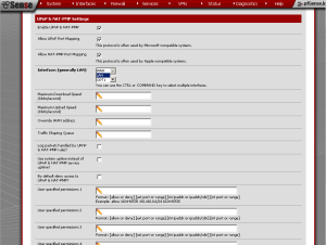
Enabling UPnP and NAT-PMP in pfSense 2.0.

As it happens, both UPnP and NAT-PMP are supported by pfSense 2.0. Enabling pfSense UPnP and NAT-PMP  is relatively easy as well. To enable these services, first navigate to Services -> UPnP & NAT-PMP. Check the “Enable UPnP & NAT-PMP” check box. Below that, check either “Allow UPnP Port Mapping“, “Allow NAT-PMP Port Mapping“, or both. At “Interfaces (generally LAN)“, select an interface (or hold down the CTRL key while clicking to select multiple interfaces). Then press the “Change” button to change the settings. You have now configured pfSense UPnP and/or NAT-PMP.


There are several additional options that are worth noting. Below “Interfaces”, you can specify a “Maximum Download Speed” (in Kbits/s). You can also specify a “Maximum Upload Speed” (also in Kbits/s). “Override WAN address” can be used to override the miniupnp listening address. “Traffic Shaping Queue” allows you to specify an already-defined traffic shaping queue (for more information, see parts one, two, and three of my series on traffic shaping). Checking “Enable Log Packets” will keep a log of UPnP and NAT-PMP traffic. Checking “Use system uptime instead of UPnP and NAT-PMP service uptime” will use the system’s uptime in the logs. Checking “By default deny access to UPnP & NAT-PNP” will block UPnP and NAT-PNP traffic except for traffic specifically allowed in the below “User specified permissions“. There, you can define up to four permissions in the following format: [allow or deny][external port or range][internal IP address or IP address/CIDR][internal port or range].

pfSense UPnP and NAT-PNP:  Potential Security Risks

Now that I have described pfSense UPnP and NAT-PNP and how to configure them, I suppose it is only fair to note that enabling these services and allowing devices to make and modify their own firewall rules has some serious security implications. In January 2013, the security company Rapid7 reported on a six-month research program in which a team scanned for signals from UPnP-enabled devices announcing their availability for internet connect. Some 6900 products from 1500 companies at 81 million IP addresses responded to their requests. 80% of the devices are home routers; others include printers, webcams, and surveillance cameras. With this in mind, it is little wonder that UPnP  is not targeted many at home routers and not enterprise-level networking equipment, as IT departments would likely be wary of deploying equipment with such glaring security vulnerabilities. I do not know of any similar studies covering NAT-PMP devices, but I would assume this has more to do with the greater popularity of UPnP than it has anything to do with NAT-PMP devices being more secure. It might be prudent to dedicate a separate interface to UPnP and/or NAT-PMP devices. It might be even more prudent to use the “By default deny access to UPnP & NAT-PNP” feature and only allow specific pfSense UPnP and NAT-PMP traffic.

External Links:

UPnP at Wikipedia

NAT-PMP at Wikipedia

What is pfSense UPnP? at doc.pfsense.org

UPnP flaws turn millions of firewalls into doorstops at nakedsecurity

The post pfSense UPnP and NAT-PMP appeared first on pfSense Setup HQ.


Video: Adding Firewall Rules

pfSense Wake-on-LAN

$
0
0
pfSense Wake-on-LAN

Configuring pfSense Wake-on-LAN in pfSense 2.0.

In this article, I cover another interesting pfSense feature: pfSense Wake-on-LAN. As you may know, Wake-on-LAN (WOL) is an Ethernet computer networking standard that allows a computer to be turned on or awakened by a network message. It was introduced in 1997 as a joint project by Intel and IBM. Wake-on-LAN is implemented using a specially designed packet called a magic packet, which is sent to the computer to be woken up. The magic packet contains the MAC address of the destination computer. Powered-downed or turned off computers capable of Wake-on-LAN will contain network devices able to listen to incoming packets in low-power mode while the system is powered down. If a magic packet is received that is directed to the device’s MAC address, the NIC signals the computer’s power supply or motherboard to initiate system wake-up, much in the same way as pressing the power button would do. The magic packet is sent on layer 2 of the OSI model (data link layer) and when sent, is broadcast to all attached devices on a given network, using the network broadcast address; layer 3 (the network layer) is not used. As a result, if you want to use Wake-on-LAN outside your current network, it requires special configuration. pfSense Wake-on-LAN provides the capability of either waking a computer from the local network or the Internet.


Enabling Wake-on-LAN on the Motherboard

In order to use Wake-on-LAN, your motherboard has to have a chipset that includes this feature. Most likely, you will have to enable Wake-on-LAN in your motherboard’s CMOS setup utility first. This is done by rebooting the computer and entering the CMOS setup utility (usually by holding down the Escape key or F2 or F10 during the boot sequence). Wake-on-LAN is usually found within “Power Management Setup” in the main menu of the CMOS setup utility. In any case, enter the appropriate submenu and scroll down until you find Wake-on-LAN (it might be called “WOL”, “Power on PCI”, or something similar), and enable it if it is not enabled already. Then save the settings and quit CMOS setup and reboot. In addition to enabling Wake-on-LAN on the motherboard, you may also have to enable it on your network card. In Windows, you can do this by browsing to the Device Manager (you can get there by navigating to Control Panel -> System, clicking on the Hardware tab, and pressing the Device Manager button, but there are other ways as well). Scroll down to your network card and double-click on it. You should be able to find the Wake-on-LAN feature by clicking on the Advanced tab and looking under Property. In Linux, you can configure your network card using the ethtool utility.

Configuring pfSense Wake-on-LAN

pfSense Wake-on-LAN

Wake-on-LAN can be invoked by clicking on the appropriate MAC address in the table, or entering the MAC address above, or clicking the button to wake all clients at once.

Now you can enable Wake-on-LAN in pfSense. To enable pfSense Wake-on-LAN, first navigate to Services -> Wake on LAN. Once there, press the “plus” button to add a WOL MAC address entry. At “Interface”, select the interface that contains the device. At “MAC address“, enter the device’s MAC address. At “Description“, add an appropriate description and press the “Save” button to save the changes. After you save the changes, it will take you back to the page you were at when you clicked on “Wake On LAN”. Here you will see a table with a list of all the stored clients. Click on the MAC address of any of the stored clients to send a magic packet, or enter the interface and MAC address at the top of the page and click on the “Send” button. In addition, there is a button in the middle of the page that will enable you to wake all the clients at once. External Links: Wake-on-LAN in Wikipedia pfSense Wake-on-LAN at doc.pfsense.org The Ultimate Wake-on-LAN Guide – contains a lot of useful information, especially about how to enable Wake-on-LAN on your motherboard. It includes a section on pfSense.

The post pfSense Wake-on-LAN appeared first on pfSense Setup HQ.

Syslog Configuration in pfSense

$
0
0

Introducing Syslog

Syslog is a standard for computer data logging. It separates the software that generates messages from the system that stores them and the software that reports and analyzes them. It was developed in the 1980s by Eric Allman as part of the Sendmail project, and proved so valuable that other applications began using it as well. Since then, Syslog has become the standard logging solution on Unix and Unix-like systems, and there have been a variety of syslog implementations on other operating systems.

Syslog initially functioned as a de facto standard, without any authoritative published specification, and many implementations existed; some of them were incompatible with each other. Eventually the Internet Engineering Task Force documented the standard in RFC 3164. It was made obsolete by subsequent additions in RFC 5424.

Centralized logging to a specific logging host can reduce some of the administrative burden of log file administration. Log file aggregation, merging and rotation acan be configured in one location using syslog. In syslog, messages are labeled with a facility code indicating what type of program is logging the message. The codes are as follows:

Facility Levels
Facility Number Keyword Facility Description
0 kem kernel messages
1 user user-level messages
2 mail mail system
3 daemon system daemons
4 auth security/authorization messages
5 syslog messages generated internally by syslog
6 lpr line printer subsystem
7 news network news subsystem
8 uucp UUCP subsystem
9 - clock daemon
10 authpriv security/authorization messages
11 ftp FTP daemon
12 - network news subsystem
13 - log audit
14 - log alert
15 cron clock daemon
16 local0 local use 0 (local0)
17 local1 local use 1 (local1)
18 local2 local use 2 (local2)
19 local3 local use 3 (local3)
20 local4 local use 4 (local4)
21 local5 local use 5 (local5)
22 local6 local use 6 (local6)
23 local7 local use 7 (local7)

For cron either 9 or 15 may be used. With auth/authpriv, 4 and 10 are commonly used but 13 and 14 can be used too.


Finally, here are the eight security levels:

Severity Levels
Code Severity Keyword Description
0 Emergency emerg (panic) System is unstable
1 Alert alert Action must be taken immediately
2 Critical crit Critical conditions
3 Error err (error) Error conditions
4 Warning warning (warn) Warning conditions
5 Notice notice Normal but significant condition
6 Informational info Informational messages
7 Debug debug Debug-level messages

A mnemonic used to remember these levels is: “Do I Notice When Evenings Come Around Early”.

Configuring Syslong in pfSense

Syslog

Configuring Syslog for remote logging under pfSense 2.0.

To configure syslog, first navigate to Status -> System Logs. From there, click the “Settings” tab. Check the “Enable syslog’ing to remote syslog server” check box to send syslog messages to a remote server. At “Remote syslog servers“, enter the IP addresses of up to three remote syslog servers. Below that, there are nine check boxes. Eight check boxes are for logging different events (system, firewall, DHCP service, portal authorization, VPN, gateway monitor, server load balancer, and wireless); the ninth check box is labeled “Everything” and will cause syslog to record all messages. Check whichever items you wish to monitor, or check “Everything” to monitor record everything. Then press the “Save” button to save the changes.

Now that we have enabled remote syslog logging, we have removed a considerable burden from the resources of the pfSense machine, which should have a positive effect. This will especially be the case if the machine is light on memory and hard disk space (or for that matter, if we are running it from the live CD and the log entries are being made to a floppy disk).

There are several other settings worth noting, which are applicable to a scenario where remote logging is not enabled. At the top of the Settings page, checking “Show log entries in reverse order” will cause the newest entries to appear on top. Checking “Log packets blocked by the default rule” (checked by default) will cause syslog to log packets blocked by the implicit default block rule. Checking “Show raw filter logs” will result in filter logs being show as generated by the packet filter, without any formatting. This will reveal more detailed information. Finally, checking “Disable writing log files to the local RAM disk” will cause syslog to stop writing logs to the RAM disk, thereby freeing up memory.

External Links:

Syslog on Wikipedia

Copying Logs to a Remote Host with Syslog at doc.pfsense.org

Custom pfSense Firewall Log Analyzer – step-by-step instructions on how to set up a custom pfSense log analyzer using shell scripts and Python code

pfSense Remote Logging to Kiwi Syslog Server – shows how to send pfSense logs to a Kiwi server running under Windows

The post Syslog Configuration in pfSense appeared first on pfSense Setup HQ.

Reader E-Mail: Gateways

$
0
0

pfsense-logo-chopped-219x160It’s the weekend, and I thought I would use it as an opportunity to catch up on e-mails for this site. I came across the following message in my inbox:

Hi, I’m enjoying reading your setup guides you have obviously put in a lot of time and effort.
In this article about gateways you haven’t really explained why you would want to add a gateway. Adding an unrequired gateway to an internal interface is a very common setup error that can cause problems for new users. In the majority of setups you would never need to manually add a gateway.
Anyway keep up the good work!

Admittedly, my article on gateways may have caused some confusion, so hopefully I can clear it up here.

In most cases, the “gateway” is simply the network interface to which remote traffic is directed. This will simply be the IP address of the router in the case of most home or SOHO networks, and we don’t need to configure anything separately; it is enough to know what the default gateway is so we can use it to set up nodes on our side of the router. In cases where DHCP is used, the systems get this information from the router used as a DHCP server, so knowing the gateway IP may not even be necessary (though helpful if something goes wrong). Assume, for example, that we have a relatively simple home network, with several computers connected to a switch, and the uplink port of the switch connected to the router. All computers on the local network have a network prefix of 192.168.1.0/24, and the router (which, we will conveniently assume, is a pfSense box) has and IP address of 192.168.1.1. Our nodes have similar IP addresses, such as 192.168.1.10, 192.168.1.11, and so on.

Let’s assume that 192.168.1.10 is sending a frame to 192.168.1.11. Since the address is local, the sending system can use Address Resolution Protocol (ARP), a protocol for resolving network layer addresses into link layer addresses, to find the MAC address of destination node. Each node maintains its own ARP table, and the MAC address may well be in that table. If it isn’t, however, the sending node can send a broadcast frame to all nodes on the local network to find out which node is 192.168.1.11. If 192.168.1.11 is online, it will respond with an ARP reply. The sending node will get the ARP reply, store the MAC address for 192.168.1.11 in its ARP table, and send a frame with the MAC address of 192.168.1.11 as the destination.

If, however, 192.168.1.10 wants to send a frame to, say, 50.87.147.42 (the address of this site), then there is a different outcome. The system should recognize this address as being outside the network. As a result, the sending system will create packets with the remote system’s IP address and create frames with the default gateway’s MAC address (this is our pfSense box at 192.168.1.1). When the default gateway receives the frame, it will strip off the frame, inspect the IP packets, wrap them in whatever type of frame the outgoing connection needs. It will then send them out through the WAN interface, in the hope that someone upstream can direct the packets to their destination.

I think this is a fairly straightforward explanation of the gateway’s role in a network, but a lot of readers of this blog may be more knowledgeable than I am and may have their own views. If anyone has anything to contribute to this discussion, feel free to comment.

The post Reader E-Mail: Gateways appeared first on pfSense Setup HQ.

pfSense Backup and Restore

$
0
0

Backing up your pfSense configuration files is a crucial task, both in order to restore the configuration after a system failure and to recover data from an earlier time. Fortunately, pfSense makes the process easy. pfSense backup configuration files are stored in a plain text XML format by default, but it also gives the user an option to encrypt them.

pfSense Backup in a Few Easy Steps

pfSense Backup

Backup configuration options in pfSense 2.0.

To backup the configuration files, first navigate to Diagnostics -> Backup/restore and from there, select the Backup/Restore tab. At “Backup area“, you will see a drop-down box showing all the configuration areas you can back up. Leave it as “ALL” to backup all files. Leave “Do not backup package information” unchecked if you do not want to backup package information. The next check box is “Encrypt the configuration file“; check this if you want to encrypt the backup (you will have to enter the password twice in the edit boxes below if this is selected). Leave “Do not back up RRD checked” unless you want to backup the round robin database (it can be over 4 MB in size). Press the “Download configuration” button and save the file to a safe location. Your pfSense backup is now complete.


Now, the configuration info will be stored in a single XML file. Some passwords, however, will be stored in plain text. If this is a problem, you can always encrypt the file with the “Encrypt this configuration file” option.

Automating Your pfSense Backup

You’re probably wondering if the backup process can be automated. As it happens, there is a package called “AutoConfigBackup” that enables you to automate backups, but it is only available for paying pfSense customers with a Premium support contract. However, Koen Zomers has created his own command line backup automation tool for Windows, which is quite easy to use (remember to use the -v 2.0 option when backing up a pfSense 2.0 configuration file). You can use this in conjunction with the AT command to fully automate the process. For example:

at 20:00 /every:M,T,W,Th,F,S,Su pfSenseBackup.exe -u admin -p password -s 192.168.1.1 -o c:\backup.xml -v 2.0

will backup the config file of the pfSense router at 192.168.1.1 to the C drive at 8:00 PM every day.

If you don’t use Windows or don’t want to use this utility, you can still automatically make a backup. When a change is made in pfSense, a backup of the configuration file is stored in /cf/conf/backup. You could create a script to run as a cron job on the pfSense system to copy this file to a remote system, or you could run a script on the remote system which could download the files.

Restoring from a Backup

You can also restore pfSense’s configuration from a backup. From the same tab under “Restore Configuration“, choose a restore area from the dropdown box, click on the “Choose” button to launch the file dialog box and select a backup configuration file. Press the “Open” button to close out the file dialog box. Click the “Configuration file is encrypted” check box if the file is encrypted (you will have to specify a password), and press the “Restore configuration” button. pfSense will reboot after “Restore configuration” is pressed.

External Links:

Configuration Backup and Restore at doc.pfsense.org

How to automate pfSense backup, where you can download Koen Zomer’s pfSense backup tool.

Remote Config pfSense Backup at doc.pfsense.org – information on how to use the Auto Config Backup package, but you need a paid subscription to use it.

How to Backup and Restore Configurations in pfSense 2.0

The post pfSense Backup and Restore appeared first on pfSense Setup HQ.

Viewing all 260 articles
Browse latest View live