Here’s another video I made, covering scheduler options in pfSense 2.0:
The post Video: pfSense Scheduler Options appeared first on pfSense Setup HQ.
Here’s another video I made, covering scheduler options in pfSense 2.0:
The post Video: pfSense Scheduler Options appeared first on pfSense Setup HQ.
I’m going to make several videos covering VPNs. This one covers IPSec; I had to rush through it a bit, but hopefully the subsequent videos will explain a bit more:
The post Video: pfSense VPN Part One (IPSec) appeared first on pfSense Setup HQ.
I posted another video today. This one covers the Layer Two Tunneling Protocol (L2TP). I probably should make another video covering RADIUS server configuration. Anyway, here it is:
The post Video: pfSense VPN, Part Two (L2TP) appeared first on pfSense Setup HQ.
Enabling SSH access in pfSense 2.0.
For today’s article, I decided to cover something I probably should have covered earlier on: how to enable Secure Shell (SSH) login in pfSense 2.0. You may never have occasion to access your pfSense box remotely outside of the web GUI, but enabling the SSH server is still a good idea just in case you do.
Secure Shell (SSH) is a cryptographic network protocol for secure data communication, remote command-line login, remote command execution, and other secure network services between two networked computers that connects via a secure channel over an insecure network, a sever and a client. Typically SSH is used for access to shell accounts on Unixoid operating systems, but it can also be used in a similar fashion for accounts on Windows. It was designed as a replacement for Telnet and other insecure remote shell protocols such as the BSD rsh and rexec protocols, which send information – including passwords – in plain text, thus rendering them vulnerable to interception and disclosure. The encryption used by SSH is intended to provide confidentiality and integrity of data over an unsecured network.
To enable the Secure Shell (SSH) service in pfSense, navigate to System -> Advanced, and scroll down to the section labeled “Secure Shell“. Check the “Enable Secure Shell” check box to enable SSH. You will be prompted for a username and password when you connect. You can use the same credentials that you use to connect to the web GUI. But if you check “Disable password login for Secure Shell“, you can use your RSA keys instead. At “SSH port“, leave the edit box blank to use the default port, or type in a different port to use a different one. If you are not going to allow SSH access to your pfSense box from the Internet, you can probably leave the default unchanged; otherwise, it is probably a good idea to choose a port a hacker is unlikely to guess, and even then, it is advisable to do any remote (i.e., from outside the network) administration through a VPN. Finally, press the “Save” button to save the changes and the pfSense SSH service will be started.
PuTTYGen in action under Windows.
Using RSA keys is one way to secure client/server connections between the client and the SSH server. In order to utilize RSA keys, you must first generate a public-private key pair using a tool such as ssh-keygen on a Linux-based system or a Mac, or a tool such as PuTTYGen on a Windows-based system. To use ssh-keygen, simply open a terminal, run ssh-keygen, and save the key (you can also specify a pass code). To use PuTTYGen, open it and press the “Generate” button to generate a public/private key pair. You can enter a passphrase in the appropriate edit box, and press “Save private key” to save the private key. You can copy and paste the public key from the text box at the top of the application’s dialog box.
Pasting a public key in the pfSense User Manager.
Once you have a public/private key pair, you need to make sure that “Disable password login for Secure Shell” is checked in the Secure Shell settings at System -> Advanced. Then navigate to System -> User Manager, and click on the “e” next to the admin listing in the table to edit settings for the admin account. Scroll down to “Authorized keys” and check the “Click to paste an authorized key” check box. Now you can paste the public key into the text box. Press the “Save” button to save the changes.
Now, when you connect to pfSense using an SSH client, you will not be prompted for a password. Instead, your client must have the private key of the public/private key pair generated earlier in order to be authenticated.
External Links:
How to Enable SSH Access at doc.pfsense.org
The SSH lockout table at doc.pfsense.org
Forum posting on safely adding SSH users to pfSense at serverfault.com
The post SSH Server Configuration in pfSense appeared first on pfSense Setup HQ.
SNMP server configuration in pfSense 2.0.
This article will (a) briefly describe the Simple Network Management Protocol, and (b) explain how to enable the SNMP server in pfSense.
Simple Network Management Protocol (SNMP) is an Internet-standard protocol for managing devices on IP networks. It is used mostly in network management systems to monitor network-attached devices for conditions that warrant administrative attention, and the protocol is supported by such devices as switches, servers, workstations, printers, modem racks, and more. SNMP is a component of the Internet Protocol Suite and consists of a set of standards for network management. It operates in the Application Layer of the Internet Protocol Suite (Layer 7 of the OSI model).
Typical SNMP use entails the following: administrative computers (called managers) have the task of monitoring or managing a group of hosts or devices on a network. Each managed system executes at all times a software component called an agent which reports information via SNMP to the manager. SNMP agents expose management data on the manged systems as variables. The protocol also permits active management tasks, such as modifying and applying a new configuration through remote modification of these variables. The variables accessible via SNMP are organized in hierarchies. An SNMP managed network consists of the following components: [1] a managed devices; [2] an agent (software which runs on the managed devices), and [3] network management system (NMS) – software which runs on the manager.
SNMP version 1 (SNMPv1) is the initial implementation of the SNMP protocol. It has been criticized for its poor security, as authentication of clients is performed only by a “community string”, in effect a type of password, which is transmitted in cleartext. The first RFCs for SNMP appeared in 1988 (1065-1067). These were obsoleted by RFCs 1155-1157, which in turn were replaced by RFC 1213. SNMPv2 (RFCs 1441-1452) revises version 1 and includes improvements in the areas of performance, security, confidentiality, and manager-to-manager communications. It introduced GetBulk Request, and alternative to iterative GetNextRequests for retrieving management data. Like version 1, however, SNMPv2 lacks encrypted connections.
// ]]>
To enable the SNMP server, first navigate to Services -> SNMP. At “SNMP Daemon“, click on the “Enable” check box (at the right). At “Polling Port”, you can probably leave this port set to the default of 161. At “System Location“, specify a location, and below that, specify a “System Contact” if desired. At “Read Community String“, specify an alphanumeric string. This is roughly equivalent to a password and changing its value will ensure only authorized SNMP clients will be able to query the SNMP information from this machine.
The second section on the page is labeled “SNMP Traps“. These traps are sent by SNMP-enabled devices to specified servers when a significant event occurs. SNMP trap servers then decide how to process and handle the even, such as e-mailing a network administrator. SNMP traps thus enable network administrators to react quickly to potential issues. To enable pfSense SNMP traps, check the “Enable” check box to the right. At “Trap Server Name“, specify the name (or IP address) of the trap server. At “Trap Server Port“, specify the port. At “Specify Trap String“, specify a string.
The third section on the page is labeled “Modules“. At “SNMP Modules“, select the modules to be queried. The fourth section, “Interface Binding“, allows you to select which interfaces the SNMP server binds to. This is useful, for example, if you are accessing your pfSense box via a VPN tunnel, and you otherwise would not be able to query the SNMP server because your IP address is that of the LAN IP address. Binding the SMTP server to LAN, which then would cause it to only listen on the LAN IP address, would solve this problem. Otherwise, you can probably leave this set to “All”. Once you are done configuring settings, press the “Save” button to save the changes. Now that the SNMP server has been enabled, administrators will be able to query vital system information from an SNMP client.
Simple Network Management Protocol at Wikipedia
SNMP Server Daemon at doc.pfsense.org
Command line examples for monitoring a pfSense router with SNMP
The post SNMP Server Configuration in pfSense appeared first on pfSense Setup HQ.
This is the third in my series of videos on VPNs; this video covers OpenVPN and will be continued in the next video:
The post Video: pfSense VPN Part Three (OpenVPN Pt. 1) appeared first on pfSense Setup HQ.
A pfSense system can be updated through the web interface. This will let you update the router to a new version so it stays current and supported. Firmware updates are issued periodically to fix bugs, address security issues, and add features.
Updating the firmware manually in pfSense 2.0.
To update the firmware, first navigate to System -> Firmware. Click on the “Auto Update” tab (the second of three tabs). Press the “Invoke Auto Upgrade” button and observe the download status in the text window. Once the download is complete, pfSense will upgrade itself and reboot. On the first login after the system has been rebooted, you will be redirected to the Package Manager status page. Assuming pfSense was able to contact pfsense.org, download the firmware and did not have any issues with installation, the firmware update is now complete.
pfSense also allows for a manual firmware update. First, download the appropriate firmware version from pfsense.org and save it locally. Then navigate to System -> Firmware and click on the “Manual Update” tab (the first of three tabs). On the next page, click the “Choose” button to browse for the firmware you have downloaded. Once you have selected the correct file, press “Open” in the file dialog box. Then press the “Upgrade firmware” button.
While the firmware is being upgraded, any attempt to access the pfSense web interface will redirect you to a page informing you that an upgrade is in progress and that the firewall will reboot when the upgrade is complete. If a new version of pfSense is available, an “Update available” notification will be displayed on the “Status: Dashboard” homepage, in the “Version” section of “System Information“.
pfSense Firmware Update Documentation at doc.pfsense.org
Upgrade pfSense 2.0 from RC1 to RC3
Video on upgrading pfSense 2.0 from RC1 to RC2 (from YouTube)
The post Firmware Update with pfSense appeared first on pfSense Setup HQ.
![]() Before you set up your pfSense system, you probably want to consider pfSense hardware requirements. The two main factors that will determine your requirements are:
Before you set up your pfSense system, you probably want to consider pfSense hardware requirements. The two main factors that will determine your requirements are:
If you require less than 10 Mbps of throughput, then even a Pentium I with a 100 MHz CPU will do. If you require greater throughput, the official pfSense website has the following guidelines (they assure us that the guidelines offer a bit of breathing room):
| Throughput | Minumum CPU Speed | Minimum Interface |
|---|---|---|
| 10-20 Mbps | 266 MHz | PCI |
| 21-50 Mbps | 500 MHz | PCI |
| 51-200 Mbps | 1 GHz | PCI |
| 201-500 Mbps | 2 GHz | PCI-X or PCI-e |
| 501+ Mbps | 3 GHz | PCI-X or PCI-e |
// ]]>
Virtually all network cards are supported by pfSense, but not all network cards are created equal. Intel Pro 100/1000 NICs have solid driver support in FreeBSD. NICs such as the Realtek 8139, however, do not perform as well and may require slightly more overhead. Moreover, with some NICs, there are some things that may not work properly at all, such as VLANs or promiscuous mode required for bridging. Generally if you are buying NICs for a new deployment, Intel Pros are the most reliable.
In addition to these guidelines, pfSense’s hardware sizing guidance page mentions the following about pfSense features and how they may relate to pfSense hardware requirements:
To show how these pfSense hardware requirements work in practice, let’s assume we want to set up a pfSense box for a small office. The office has a 50 Mbps net connection; we want to anticipate future use, but we don’t anticipate the office getting a connection faster than 100 Mbps in the forseable future. We also anticipate making use of VPNs for remote connections to the office, but we don’t plan on having more than a few VPN connections at any given time. Of the packages available, we opt to install Snort. From this information, we can determine our minimum hardware requirements:
If we want to have a failover for the firewall, our requirements would include a second machine to be used as a failover. Keep in mind that the firewall’s throughput is only a bottleneck for traffic passing through it. Traffic to and from the Internet from the LAN and the DMZ meet that requirement, as does traffic between the LAN and the DMZ. Traffic between two systems on the LAN, however, or two systems on the DMZ would not be affected.
This is my take on minimum pfSense hardware requirements, but those of you who have experience in deploying pfSense firewalls may have a different take on this. If so, feel free to add your own comments on this subject.
External Links:
pfSense Hardware Requirements and Sizing Guidance at pfsense.org
VPN Protocol Comparison List – provides some guidance as to overhead for the different protocols
How to speed up IPSec, hardware encryption devices? at forum.pfsense.org
The post pfSense Hardware Requirements appeared first on pfSense Setup HQ.
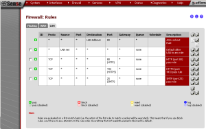
Adding a rule to allow HTTP traffic from the LAN in pfSense 2.0.
In computer networking, egress filtering is the practice of monitoring and potentially restricting the flow of information outbound from one network to another. Typically it is information from a private TCP/IP computer network to the Internet that is controlled. pfSense, like nearly all similar commercial and open source solutions, comes with a LAN rule allowing everything from the LAN out to the internet. Allowing such outbound traffic indiscriminately is not a very good idea, even though it has become the default in most firewalls, because allowing such traffic is what most users expect.
Egress filtering can be challenging, as it will increase the administrative burden, as each new application or service may require opening additional ports. It may even be cost-prohibitive in large organizations to do so. Nevertheless, you should strive to allow only the minimum amount of traffic to leave your system, for the following reasons:
The firewall rules table after the rules for port 80, 443 and 25 have been added.
As an example of egress filtering, here is an instance in which we will explicitly allow necessary traffic and disable everything else. Assume for purposes of this example that we have identified the following requirements:
| Rule | Source IP | Destination IP | Destination port |
|---|---|---|---|
| HTTP and HTTPs | any | any | TCP 80 and 443 |
| SMTP from mail server | Mail server IP | any | TCP 25 |
Thus, we want to allow outbound HTTP, HTTPS and SMTP traffic and nothing else.
// ]]>
First, navigate to Firewall -> Rules. Select the “LAN” tab to create a new LAN rule. Note that unless you have made changes, there should be a “Default allow LAN to any rule” already there. Click on the “plus” button to add a new rule. Leave “Action” set to “Pass” and “Interface” set to “LAN”. Leave “Protocol” set to “TCP”. Set both “Source” and “Destination” to “any”, and set “Destination port range” to “HTTP”. At “Description“, type an appropriate description and press the “Save” button to save the changes; then press the “Apply changes” button to apply changes if necessary.
Disabling the default allow LAN to any rule.
To create the rules for ports 443 and 25, repeat the above steps twice, substituting “HTTPS” for “Destination port range” the first time, and “SMTP” the second time. Once the new rules are added, all that is left to do is disable the “Default allow LAN to any” rule. Click on the “e” next to this rule, and next to “Disabled“, check the “Disable this rule” check box. Then click on “Save” to save the changes and “Apply changes” to apply the changes.
Now, all outbound traffic from the LAN except for these 3 ports will be blocked. This may make the admin’s job somewhat more challenging, but it should reduce the chances that malware or spam bots gain a foothold on your network.
Egress Filtering FAQ – an excellent whitepaper on egress filtering from the SANS Institute
Performing Egress Filtering – another whitepaper on egress filtering
Egress filtering on WhatIs.com
Firewall Best Practices – Egress Traffic Filtering from The Security Skeptic
The post Egress Filtering with pfSense appeared first on pfSense Setup HQ.
![]() I should have done this before, but I’ve created a Facebook page for pfSense Setup HQ. There are links to the latest articles posted to this site, and I’m looking forward to adding more content to the page soon.
I should have done this before, but I’ve created a Facebook page for pfSense Setup HQ. There are links to the latest articles posted to this site, and I’m looking forward to adding more content to the page soon.
I also started a Twitter account for this site, which may be more convenient for those who just want to get tweets whenever a new article is posted.
The post pfSense Setup HQ on Facebook (and Twitter) appeared first on pfSense Setup HQ.
The Services list shows the NTP service is running.
The Network Time Protocol daemon (NTPD) is an operating system daemon that maintains the system time with time servers, using the Network Time Protocol. It is a complete implementation of the Network Time Protocol version 4, but retains compatibility with previous versions of NTP. NTPD performs most computations in 64-bit floating point arithmetic and uses 64-bit fixed point operations only when necessary to preserve the ultimate precision. The Network Time Protocol needs some reference clock that defines the true time to operate. All clocks are set towards that true time. NTP is a fault-tolerant protocol that will automatically select the best of several available time sources to synchronize to. Multiple candidates can be combined to minimize the accumulated error. Temporarily or permanently bad time sources will be detected and avoided. Having available several time sources (there are at least 175,000 hosts running NTP servers), NTP can select the best candidates to build its estimate of the current time. The protocol is highly accurate, using a resolution of less than a nanosecond. And even when a network connection is temporarily unavailable, NTP can use measurements from the past to estimate current time and error.
// ]]>The official specification of NTP version 3 is RFC 1305. According to the NTP Version 4 Release Notes, the new features of version four are:
You can edit the NTP server settings at System -> General Setup.
Enabling OpenNTP in pfSense is relatively easy. First, make sure the pfSense system’s clock is set and is reasonably accurate. If not, synchronization may fail because if there is a substantial difference between the system time and the time reported by the NTP server, the daemon will assume the server is wrong and not the other way around. Then navigate to Services -> NTP. At “Interface“, select the interface(s) the NTP daemon service will listen on (hold down CTRL while clicking to select multiple interfaces). Then press the “Save” button to save the changes. Now, NTP synchronization will be enabled on your pfSense box, but client machines can take up to a few hours (doc.pfsense.org reports 1-2 hours) to become fully synchronized with the OpenNTPD service.
If you want to edit the list of NTP time servers, navigate to System -> General Setup. Under the “System” heading, the last option is “NTP time server“. Here you can specify one or more time servers (use a space to specify multiple hosts). Then press the “Save” button to save the settings.
Network Time Protocol on Wikipedia
ntp.org – home of the Network Time Protocol project
The Network Time Protocol Distribution NTP Server at doc.pfsense.org
Use pfSense as an NTP Server – another post from the excellent iceflatline blog.
How to Set Up an NTP Server for Your Network
Using pfSense and OpenNTPD – a how-to guide from HubPages.
The post NTP Configuration in pfSense appeared first on pfSense Setup HQ.
I recorded another video; this one covers Point-to-Point Tunneling Protocol:
The post Video: pfSense VPN, Part Four (PPTP) appeared first on pfSense Setup HQ.
Enabling Routing Information Protocol (RIP) in pfSense.
The Routing Information Protocol (RIP) is one of the oldest distance-vector routing protocol, which employs the hop count as a routing metric. RIP prevents routing loops by implementing a limit on the number of hops allowed in a path from the source to a destination. The maximum number of hops (one portion of the path between source and destination; each time packets are passed to the next device, a hop occurs) allowed for the protocol is 15. This limit, however, also limits the size of networks that RIP can support (a hop count of 16 is considered unreachable).
RIP implements several algorithms to ensure incorrect routing information from being propagated. As a result, it is considered relatively stable. Using RIP, a gateway host sends its entire routing table, which lists all the other hosts it knows about, to its closest neighbor host every 30 seconds. The neighbor host in turn will pass the information on to its next neighbor and so on until all hosts within the network have the same knowledge of routing paths, a state known as network convergence. As networks increased in size, it became evident there could be a massive traffic burst every 30 seconds, even if the routers had been initialized at random times.
RIP uses the User Datagram Protocol (UDP) as its transport protocol, and is assigned the reserved port number 520. The original specification of RIP was defined in RFC 1058 and uses classful routing. The periodic routing updates do not carry subnet information and lack support for variable length subnet masks, making it impossible to have different-sized subnets inside the same network class. RIP version 2 was developed in 1993 and last standardized in 1998. It included the ability to carry subnet information and also multicasts the routing table (to 222.0.0.9) instead of broadcasting the table, to avoid unnecessary load on hosts that do not participate in routing. It is defined in RFC 2453. To maintain compatibility with version 1, the maximum number of hops is still 15. RIPng, defined in RFC 2080, incorporates several improvements over version 2, including support for IPv6 networking, attaching arbitrary tags to routes, and sending updates on UDP port 521. pfSense does not seem to currently support RIPng.
The major alternative to RIP is the Open Shortest Path First Protocol, which was discussed in a previous blog posting. Other alternatives include Cisco’s proprietary Interior Gateway Routing Protocol (IGRP), a distance-vector routing protocol, and its replacement, Enhanced Interior Gateway Routing Protocol (EIGRP).
To enable RIP in pfSense, first navigate to Services -> RIP. At “Enable RIP”, check the check box. At “Interfaces”, select at least one interface (hold CTRL down while clicking to select multiple interfaces). At “RIP Version”, select either RIP Version 1 or Version 2. At “Password”, set a password if using RIP version 2. Finally, press the “Save” button to save the changes.
// ]]>
Routing Information Protocol at Wikipedia
Routing Information Protocol (RIP) at doc.pfsense.org
Routing Information Protocol (RIP)”>Routing Information Protocol at SearchNetworking
Introduction to Routing Information Protocol (RIP) on YouTube
The post Routing Information Protocol Setup in pfSense appeared first on pfSense Setup HQ.
![]() I decided to write a follow-up to the article on RIP to clarify some issues. RIP version 1 does not support classless routing, whereas RIP version 2 does. To understand the implications of this, consider the historical classful network architecture. A class A network has an 8-bit network ID and the first octet is from 0 to 127. A class B network has a 16-bit network ID and the first octet is from 128 to 191. A class C network has a 24-bit network ID and the first octet is from 192 to 223. This system served its purpose in the early stages of the Internet, but it lacked scalability in the face of the rapid expansion of the network in the 1990s. The class system of the address space was replaced with Classless Inter-Domain Routing (CIDR) in 1993. CIDR is based on variable length subnet masking (VLSM) to allow allocation and routing based on arbitrary-length prefixes.
I decided to write a follow-up to the article on RIP to clarify some issues. RIP version 1 does not support classless routing, whereas RIP version 2 does. To understand the implications of this, consider the historical classful network architecture. A class A network has an 8-bit network ID and the first octet is from 0 to 127. A class B network has a 16-bit network ID and the first octet is from 128 to 191. A class C network has a 24-bit network ID and the first octet is from 192 to 223. This system served its purpose in the early stages of the Internet, but it lacked scalability in the face of the rapid expansion of the network in the 1990s. The class system of the address space was replaced with Classless Inter-Domain Routing (CIDR) in 1993. CIDR is based on variable length subnet masking (VLSM) to allow allocation and routing based on arbitrary-length prefixes.
| Class | First Decimal Value | Addresses | Hosts per Network |
|---|---|---|---|
| Class A | 1-128 | 1.0.0.0-128.0.0.0 | 16.7 Million |
| Class B | 128-191 | 128.0.0.0-191.255.255.255 | 65534 |
| Class C | 192-223 | 192.0.0.0-223.255.255.255 | 254 |
| Class D | 224-239 | 224.0.0.0-239.255.255.255 | Multicast addresses |
| Class E | 240-255 | 240.0.0.0-255.255.255.255 | Experimental addresses |
The advantages of classless networks should be obvious. Assume we currently have one class C network: 192.168.1.0. We have 100 hosts, and we would like to split our network into two separate networks, each with 50 hosts. We could set up a new network at 192.168.2.0. This would be overkill, however, since each network allows for 254 hosts (all permutations of 1s and 0s in the final octet except 0 and 255, as we don’t want addresses that are all ones or zeros). A potentially better solution would be to divide 192.168.1.0 into two separate subnets. To do this, we move our netmask two bits to the right. Doing this gives us 4 new combinations, but 2 of them are useless – 00 and 11 – so we are left with 01 and 10 as the rightmost bits of our two subnets. The subnet masks for our networks are 192.168.1.128 and 192.168.1.192, or in CIDR notation, 192.168.1.128/26 and 192.168.1.192/26.
// ]]>
Where it becomes a problem is if we are running RIP version 1. Let’s assume we have a router (Router A) for our first subnet (192.168.1.128) and a router (Router B) for our second subnet (192.168.1.192). Let’s further assume that there is a third router (Router C) with a path to both routers. RIP version 1 uses classful subnetting, so it will look at the first octet to determine what the subnet mask is. In this case, it will see that the first octet is 192, and assume it is a class C network with a subnet mask of 255.255.255.0. It will update the routing tables to show Router A and B both with a network ID of 192.168.1.0. Router C will then assume that it has two paths to the same network (instead of paths to 2 separate networks), and, as a result, if it wants to send an update to, say, 192.168.1.194 (which is on Router B’s subnet), it may send the update to Router A instead.
Since we probably don’t want to abandon classless networking, the solution is to use RIP version 2, or RIPng (an extension of RIP version 2). Each supports classless networking and therefore will allow us to create new subnets.
Classless Inter-Domain Routing at Wikipedia
The post Routing Information Protocol: Notes appeared first on pfSense Setup HQ.
Dyanmic DNS (DDNS) is a method of automatically updating a name server in the Domain Name System (DNS), often in real time, with the active DNS configuration of its configured hostnames, addresses or other information. The term is used in two different ways. At the administrative levels of the Internet, “dynamic DNS updating” refers to systems that are used to update traditional DNS records without manual editing. But another type of dynamic DNS permits lightweight and immediate updates to its local database, often using a web-based mechanism. It is used to resolve a domain name to an IP address that may change frequently, thus providing a persistent addressing method for devices that change their location or configuration.
It is the latter type of DDNS in which we are interested. End users of Internet access receive an allocation of IP addresses, often only a single address, by their service providers. If you are a residential or small business customer, you will probably have an IP address assigned dynamically. Such dynamic IP addresses present a problem if the customer wants to provide a service to other users, such as a website. As the IP address may change frequently, corresponding domain names must be quickly re-mapped in the DNS servers to maintain accessibility using a well-known domain name. To this end, many providers offer commercial or free DDNS service for this scenario, with reconfiguration generally implemented in the user’s router or computer.
// ]]>
Dynamic DNS providers offer a software client program that automates the discovery and registration of the client system’s public IP addresses. The client program connects to the DDNS provider from the client’s private network and links the public IP address of the home network with a hostname. Depending on the provider, the hostname is registered with a domain owned by the provider or the customer’s own domain name. These services can function by a number of mechanisms. Often the use an HTTP service request. The provider might use RFC 2136 to update the DNS servers (more on RFC 2136 later). Many home networking modem/routers have clients for several DDNS providers built into their firmware, and pfSense is no exception, making it very easy to use DDNS with pfSense.
Configuring the DDNS client in pfSense 2.0.
To enable DDNS in pfSense, first navigate to Services -> Dynamic DNS. If the “DynDNS” tab is not selected already, click on it. Press the “plus” button on the right side of the page to add a new DDNS client. At “Service type“, select a DDNS service provider from the dropdown box. At “Interface to monitor“, specify an interface (typically the WAN). At “Hostname“, specify the hostname (either one supplied by the provider or your own hostname) that you wish to associate with your network’s public IP. At “MX“, set your MX record if you need one (thus allowing you to configure your subdomain for email routing) and if your service supports it. At “Wildcards“, enable wildcards if desired. This is useful if the domain name specified is not a fully qualified domain name (FQDN); for example, if your DDNS address is myplace.dyndns.org and you enable wildcards, then x.myplace.dyndns.org will work as well (x is the wildcard). At “Username” and “Password“, specify your username (username is required for all types except Namecheap and FreeDNS) and password. At “Description“, enter an appropriate description. Then press the “Save” button to save the settings and, on the next page, press “Apply Changes” to apply the changes if necessary.
If our DDNS service provider is not one of the pre-configured ones, we can still use pfSense to act as a client for the provider if it complies with RFC 2136.
To make sure everything is working go back to Services -> Dynamic DNS. If the cached IP is green then the hostname was successfully updated. It is also probably a good idea to ping the domain to make sure the domain name resolves to the correct IP address. Even with DDNS, it can take several minutes for the changes to propagate to other DNS servers. The client will automatically update the dynamic host each time the WAN IP changes or every 25 days. You probably want to make sure your client is connecting to the service, since some providers will remove inactive hosts if they have not been updated for 30 days.
This configuration will work in most cases; however, it is possible you may be using a DDNS service provider that is not on the list at “Service type“. If this is the case, you can still use pfSense to to connect to your DDNS provider as long as the provider adheres to the RFC 2136 standard. To enable this, navigate to Services -> Dynamic DNS as before, but select the RFC 2136 tab. Press the “plus” button to add a new entry. Specify the “Interface to monitor” and “Hostname” as outlined in the instructions for the “DynDNS” tab. You can also specify a time to live for data from our client at “TTL“. You must also specify a “Key Name” that matches the key name setting on the DNS server, a “Key type” (zone, host, or user), and an HMAC-MD5 “Key“. You must specify the server address at “Server“. Check the check box at “Protocol” if the DDNS provider uses TCP instead of UDP. At “Description“, enter an appropriate description. Then press the “Save” button to save the changes and “Apply changes” to apply changes if necessary.
Dynamic DNS on doc.pfsense.org
RFC 2136 Dynamic DNS on doc.pfsense.org
How to Configure Dynamic DNS in pfSense at HubPages
The post Dynamic DNS Configuration in pfSense appeared first on pfSense Setup HQ.
The Internet Group Management Protocol (IGMP) is a communications protocol used by hosts and adjacent routers on IP networks to establish multicast group memberships. IGMP operates between the client computer and a local multicast router. Like other network management protocols, it operates above the network layer. There are three versions of IGMP: version 1, defined by RFC 1112, version 2, defined by RFC 2236, and version 3 was initially defined by RFC 3376 and has been updated by RFC 4604. A router can serve as an IGMP proxy, as we shall soon see.
The IPv4 address scheme assigns Class D addresses for IP multicasting. IGMP is the protocol that uses these addresses. The following addresses have specific functions or are unavailable:
This implementation of IGMP complies with IGMPv2, which involves the exchange of the following types of messages between routers and hosts:
A multicast router can be a querier or a nonquerier. There is only one querier on a network at any time. Multicast routers monitor queries from other multicast routers to determine the status of the querier. If the querier hears a query from a router with a lower IP address, it relinquishes its role to that router.
Multicast routers send two types of group membership queries to hosts on the network: [1] general queries to the all-hosts group address, and [2] specific queries to the appropriate multicast group address. The purpose of a membership group query is to discover the multicast groups to which a host belongs. When a host receives such a query, it identifies the groups associated with the query and determines to which groups it belongs. Since the query has a Max Response Time field (the maximum time a host can take to respond to a query), the host sets a timer less than this field, and when the timer expires, the host muliticasts a group membership report to the group address. When a multicast router receives a report, it adds the group to the membership list for the network and sets a timer to the Group Membership Interval. If this timer expires before the router receives another group membership report, the router determines that the group has no members left on the network. If the router does not receive any reports for a specific multicast group within the Max Response Time, it assumes that the group has no members on the network. The router does not forward subsequent multicasts for that group to the network.
New to IGMP version 2 are the leave group membership messages. When a host leaves a group, it sends such a message to multicast routers on the network. A host generally addresses leave group membership messages to the all-routers group address, 222.0.0.2.
The IGMP protocol is implemented on a particular host and within a router. A host requests membership to a group through its local router while a router listens for these requests and periodically sends out subscription queries.
IGMP proxy configuration in pfSense. Here, we configure the upstream interface.
IGMP proxy configuration is relatively simple. You enable IGMP proxy on one interface, which connects to a router closer to the root of the tree. This interface is the upstream interface. The router on the upstream interface should be running IGMP. You also enable IGMP on the interfaces that connect the system to its hosts that are farther away from the root of the tree. These interfaces are known as downstream interfaces. When you configure IGMP proxy, the system interacts with the router on its upstream interface through the exchange of IGMP messages. However, when acting as the proxy, the system performs the host portion of the IGMP task on the upstream interface as follows:
IGMP Proxy page showing the upstream and downstream interfaces.
To configure IGMP Proxy in pfSense, first navigate to Services -> IGMP Proxy. Click on the “plus” button to add a new interface. To configure the upstream interface, select “WAN” in the “Interface” dropdown box. Then at “Description“, add an appropriate description. For “Type“, select “Upstream Interface”. At “Threshold“, you can set a time to live (TTL) threshold (the default is 1). At “Network(s)“, press the “plus” button and add one or more networks (along with the number of bits in the network name at the “CIDR” dropdown box). This defines which subnets are allowed to communicate via the IGMP proxy. I set it to “0.0.0.0″ for the network and “0″ for the CIDR to allow all outside hosts to send IGMP messages, but you can change this setting if necessary. Then press “Save” to save the new interface, and “Apply changes” on the next page.
Now you need to configure the downstream interface. Click the “plus” button again. At “Interface“, choose the interface on which the hosts will belong to a multicast group (probably LAN). At “Description, type an appropriate description, and at “Type“, select “Downstream Interface” from the dropdown box. At threshold, define a TTL threshold if necessary. At “Network“, click on the “plus” button and specify at least one network name and CIDR. Then press “Save” to save the changes and “Apply changes” to apply the changes.
Internet Group Management Protocol at Wikipedia
The post IGMP Proxy Configuration in pfSense appeared first on pfSense Setup HQ.
Address Resolution Protocol (ARP) is a protocol used for resolution of network layer addresses into link layer addresses. It was defined by RFC 826 in November 1982. ARP is used to convert an IP address to a physical address (the RFC specifies a 48-bit Ethernet address, called the MAC address). The RFC also specifies 10 Mb Ethernet, but ARP applies to all variants of Ethernet, regardless of speed.
To demonstrate how ARP works, let’s assume that we have two systems on our local network: NODE1 (192.168.1.10) and NODE2 (192.168.1.11). NODE1 wants to send data to NODE2. It knows the IP address, but it does not know the MAC address, and without the MAC address, it cannot make a frame. So NODE1 sends out a broadcast frame to the broadcast address, which is FF:FF:FF:FF:FF:FF. All systems on the network receive and process frames sent to the broadcast address. This frame asks all systems on the local network what the MAC address for IP address 192.168.1.11 is. This frame is called an ARP request. The system with the IP address 192.168.1.11 replies to NODE1 with an ARP reply.
Once NODE1 gets the MAC information for NODE2, it stores this information in a cache. You can see the ARP cache in your Windows or Linux system by typing arp -a (in Unixoid environments, you may have to specify the path; e.g. /sbin/arp -a). In some situations, a computer knows the MAC address, but needs the system’s IP address; in those cases, it can broadcast a Reverse ARP (RARP) command. While ARP is fairly common, few applications require RARP.
ARP is an essential networking component, but it will not work if the target computer is not part of the local network. If NODE1 wanted to send data to a remote computer, it cannot ARP that system, because the Internet does not allow any form of broadcast frames. In this case, NODE1 creates frames with the remote system’s IP addres and runs an ARP to determine the MAC address of the remote system. The sending system’s network interface card (NIC) then creates frames with the gateway’s MAC address. As each frame comes into the gateway, it strips off the frame, leaving the IP packets, which still have the IP address of the remote system as its destination. The gateway then wraps the IP packets in whatever type of frame the outgoing connection needs and sends them toward the intended system.
Viewing the ARP table in pfSense.
To view the pfSense ARP table, navigate to Diagnostics -> ARP Table. The table will contain some, but not necessarily all, of the systems in pfSense’s local network. Only systems that have been the target of an ARP query show up in the table.
Because ARP does not provide methods for authenticating ARP replies on a network, ARP replies can come from systems other than the one with the required Layer 2 address. An ARP proxy is a system which answers the ARP request on behalf of another system for which it will forward traffic, normally part of the network’s design. Proxy ARP configuration in pfSense has already been detailed in a previous article.
There is one last setting that should be noted. In some cases, you may have two NICs on the same physical network, but on different subnets. Everything works, but you get a lot of messages like this in the system log:
kernel: arp: 192.168.1.10 is on fxp2 but got reply from 00:30:ab:0e:de:a2 on fxp0
You can ignore these error messages, but because of the sheer amount of them, they may hide some of the more important error messages. Fortunately, pfSense has provided an easy way of getting rid of them. Navigate to System -> Advanced, and click on the “Networking” tab. Under “Network Interfaces“, check the “Suppress ARP messages” check box. Now ARP log messages will be suppressed between multiple interfaces on the same broadcast domain, even if they are on separate subnets.
// ]]>
Address Resolution Protocol at Wikipedia
Ethernet Address Resolution Protocol at tools.ietf.org
Switch management on two interfaces at forum.pfsense.org
The post ARP Configuration in pfSense appeared first on pfSense Setup HQ.
Enabling packet capture from the pfSense web interface.
Packet capture is useful if you need to intercept and log traffic passing over a network. As data streams flow across the network, the sniffer captures each packet and if needed, decodes the packet’s raw data showing the values of various fields in the packet, and analyzes its content.
Ethernet sniffers can take advantage of the way Ethernet frames are transmitted. When a node sends out an Ethernet data frame, it transmits it to every other node across the write in both directions. All the other computers on the network listen to the wire and examine the frame to see if it contains their MAC address. If not, they ignore the frame. If a node sees a frame with its MAC address, it opens the frame and begins processing the data. This is a simple means of sending frames (much simpler, for example, than the way a token ring network operates), but it also means Ethernet sniffers can order an NIC to run in promiscuous mode and process all the frames it sees on the cable, regardless of their MAC address. The ability to capture all packets on the local network segment would change with the advent of switched ports, but a router can still function as a packet analyzer.
The easiest way to capture packets in pfSense is to use the built-in packet capture feature. First, navigate to Diagnostics -> Packet Capture. At “Interface“, select either the LAN or WAN interface. If you are trying to track down IP addresses in your local network, you should specify LAN; if you are trying to track down traffic originating outside you network, select WAN. At “Address Family“, you can leave it set to “Any”, but you can also filter the traffic to capture only IPv4 or IPv6 addresses. You can leave “Host Address” blank, but if you are looking for traffic from a specific address or subnet (in CIDR notation), you can specify it here. You can also specify a “Port” if you want to filter by port, or leave it blank. At “Packet Length“, you can set a maximum number of bytes of each packet that will be captured, or leave it at zero, which will cause it to capture the entire frame. At “Count“, you can set a maximum number of packets the packet capture will grab. The default value is 100, and you can enter zero for no count limit. At “Level of Detail“, you can set how much detail is displayed in the capture window after you press the “Stop” button at the bottom of the screen. If you download the capture file, however, this setting will not affect the contents of it. You can check the “Reverse DNS Loookup” check box to cause the packet capture to perform a reverse DNS lookup associated with an IP address. It can cause delay, however, for large packet captures.
Wireshark in action under Windows.
Once you have run a capture using the pfSense web interface you can use Wireshark, a free and open-source packet analyzer, for packet analysis by downloading the pcap file and loading it into the program (You can do this by navigating to File -> Open in Wireshark and loading the appropriate file). A complete overview of Wireshark and its functionality is beyond the scope of this article, but you can find the packets you are looking for by applying different filters to locate the packets for which you are looking. For example, we can limit the results to a specific IP address by navigating to Analyze -> Display Filters and clicking on the “IP address” display filter, then specifying the desired IP address.
Another possibility for packet capture analysis is to run the “tcpdump” command at the pfSense command land. Again, a complete overview of the tcpdump command is beyond the scope of this article, but suffice it to say -i denotes the interface whose packets should be captured and -w indicates that the output should be written to a file. For example:
tcpdump -i fxp1 -w output.pcap
indicates that tcpdump should capture all packets on interface fxp1 (our LAN interface) and save them to output.pcap. Omitting “-w output.pcap” would result in the output going to the screen. Specifying “host 192.168.1.1″ would limit results to traffic to and from 192.168.1.1. To analyze the logs produced by tcpdump, you could use Wireshark or a program such as tcptrace.
How to Capture Packets Using pfSense at HubPages
The post Packet Capture in pfSense appeared first on pfSense Setup HQ.
Using the Ping utility in pfSense.
Ping is a computer network administration utility used to test the reachability of a host on an IP network and to measure the round-trip time for messages sent from the originating host to a destination host. It operates by sending Internet Control Message Protocol (ICMP) echo request packets to the target host and waiting for an ICMP response. In the process it measures the time from transmission to reception and records any packet loss.
RFC 1122, which defines communication layer requirements for Internet hosts, says the following about Echo Requests and Replies:
Every host MUST implement an ICMP Echo server function that receives Echo Requests and sends corresponding Echo Replies. A host SHOULD also implement an application-layer interface for sending an Echo Request and receiving an Echo Reply, for diagnostic purposes.
An ICMP Echo Request destined to an IP broadcast or IP multicast address MAY be silently discarded.
DISCUSSION:
This neutral provision results from a passionate debate between those who feel that ICMP Echo to a broadcast address provides a valuable diagnostic capability and those who feel that misuse of this feature can too easily create packet storms.
The echo request (“ping”) is an ICMP message whose data is to be received back in an echo reply (“pong”). The host must respond to all echo requests with an echo reply containing the exact data received in the request message. The echo reply is an ICMP message generated in response to an echo request, and is mandatory for all hosts and routers.
To use the pfSense ping utility, first navigate to Diagnostics -> Ping. Then at “Host”, set the host to the IP address or hostname of the host we are trying to ping. At “Interface”, choose the interface from which to initiate the ping (WAN for remote hosts, LAN for local hosts). At “Count”, use the dropdown set the number of ping requests (anywhere from 1 to 10; the default of 3 is usually sufficient). Then press the “Ping” button to invoke the utility. Sending out ICMP echo requests is often a useful diagnostic tool; however, multi-WAN is not supported with this utility.
External Links:
RFC 1122 (which mandates that Internet hosts reply to ICMP echo requests)
The post Ping Utility in pfSense appeared first on pfSense Setup HQ.
![]() Ethernet was developed at Xerox PARC between 1973 and 1974, and was developed as a network technology based on a bus topology. It was originally based on the idea of computers communicating over a shared coaxial cable, and the original specification enabled them to transfer data at a rate of up to 3 Mbps. It remained a largely in-house technology within Xerox until 1979, when Xerox decided to look for partners to help promote Ethernet as an industry standard. They worked with Digital Equipment Corporation (DEC) and Intel to publish what became known as the Digital-Intel-Xerox (DIX) standard. These companies then transferred control of the Ethernet standard to the IEEE, which in turn created the now famous 802.3 committee that continues to control the Ethernet standard. The 802.3 standard initially specified communications over coaxial cable at speeds up to 10 Mbps. Since then, Ethernet has evolved from a single network technology into a standard for a family of network technologies that share the same basic bus topology, frame type, and network access methods.
Ethernet was developed at Xerox PARC between 1973 and 1974, and was developed as a network technology based on a bus topology. It was originally based on the idea of computers communicating over a shared coaxial cable, and the original specification enabled them to transfer data at a rate of up to 3 Mbps. It remained a largely in-house technology within Xerox until 1979, when Xerox decided to look for partners to help promote Ethernet as an industry standard. They worked with Digital Equipment Corporation (DEC) and Intel to publish what became known as the Digital-Intel-Xerox (DIX) standard. These companies then transferred control of the Ethernet standard to the IEEE, which in turn created the now famous 802.3 committee that continues to control the Ethernet standard. The 802.3 standard initially specified communications over coaxial cable at speeds up to 10 Mbps. Since then, Ethernet has evolved from a single network technology into a standard for a family of network technologies that share the same basic bus topology, frame type, and network access methods.
Developing a networking standard at the physical level and beyond requires designing a way to send data, a way to determine which computer should use the shared cable at what time, and identify the sending and receiving computers. Ethernet deals with the first two issues by using a process called Carrier Sense Multiple Access with Collision Detection (CSMA/CD), and deals with the third issue by using data frames that contain Media Access Control (MAC) addresses to identify computers on the network. Carrier sense means that each node using the network examines the cable before sending a data frame. If another machine is using the network, then the node will detect traffic on the segment, wait a few milliseconds, and then recheck. If it detects no traffic, the node will send out a frame of data.
Multiple access means that all machines have equal access to the cable. If the line is free, any Ethernet node may begin sending a frame. It does not matter what function the node is performing. Ethernet assigns access on a first-come, first-serve basis, leaving it to other networking technologies (such as pfSense) to discriminate based on what type of traffic it is.
If two computers try to use the cable simultaneously, then a collision occurs, and both of the transmissions are lost. At the same time the network interface is sending a frame, it compares the data being sent with the data received over the cable. If there is a difference, both nodes will detect a collision and immediately stop transmitting. Then each node generates a random number to determine how long it waits to begin trying again. Whichever node generates the lowest number begins retransmission first. The losing node sees traffic on the wire and waits for the wire to be free again before attempting to retransmit.
As you can imagine, any Ethernet node will waste some time dealing with collisions instead of sending data. Moreover, as more nodes are added to the network, the collisions increase. We call a collision domain a group of nodes that hear each other’s traffic. Ethernet standards dictate that within a collision domain, there should be at most 5 segments tied together with 4 repeaters, and no more than 3 populated segments.
Ethernet requires a means of identifying sending and receiving nodes, and its method is to use special 48-bit binary addresses known as MAC addresses. MAC addresses give each network interface card (NIC) a unique address. When a computer sends out a data frame, all other NICs on the collision domain listen to the wire and examine the frame to see if it contains their MAC address. If not, they ignore the frame. If a NIC sees a frame with its MAC address, it accepts the frame and begins processing the data.
One issue with this method is that any device connected to the network cable can potentially capture any data frame transmitted across the wire. Network diagnostic programs can order a NIC to run in promiscuous mode, in which case the NIC will process all frames it sees on the cable regardless of their MAC addresses. Such programs are useful diagnostic tools but also pose a security risk, as anyone with access to the network can potentially intercept every frame on the collision domain.
The post Ethernet Fundamentals appeared first on pfSense Setup HQ.